The Project
The Phony Walkman: a device similar in appearance to a classic 1970s Walkman, but smartphone-compatible. The smartphone plugs into a USB-C connection point at the button of the device, which connects the phone to the audio system and controls. The Phony Walkman has large, pleasingly pushable buttons for the user to play, pause, and roll-track. The casing has a small door on the front that swings open to expose the phone screen, should the phone need to be used while inside the Phony Walkman.

The Circuit
The electronics for the audio circuit are fairly simple and easily assembled with basic breadboard components. The most crucial element is the 3.5mm audio jack with 3 rings (TRRS) wrapping the metal plug. The 2 ring (TRS) option does not interface with the circuit correctly, with the momentary buttons causing random, unpredictable affects on the music output.

The basic circuit, sans control buttons. The music from the phone plays through the breadboard and out of the speakers (not pictured).
Building the Circuit
To construct the working circuit, I cut a headphone extension cord in the middle, stripped the protective covering, and scraped off the enamel coating from the 4 internal wires.
Copper - Ground
Red - Right
Blue - Left
Green - Microphone

To splice the audio cable into the circuit, I cut colored jumper wires in half, stripped the rubber coating to expose the wires, and soldered the jumper wires to each of the 4 headphone wires.

The full audio circuit! Left, right, and ground wires are plugged into the positive and negative channels to each side. The mic wires are plugged into row 16, which connects the audio channel to the push button controls. The blue button is pause-play-skip, the red and yellow buttons are both volume-down, and the green button is volume-up.

Designing the Printed Circuit Board


Compare the beauty and simplicity of the PCB (printed circuit board) in the left photo to the rainbow spaghetti nightmare in the middle. I made an attempt at using a soldering breadboard and jumper wires one evening when my concern over the tariffs overwhelmed me, but this attempt was abandoned after about 8 hours of work.
EASYEDA
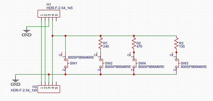
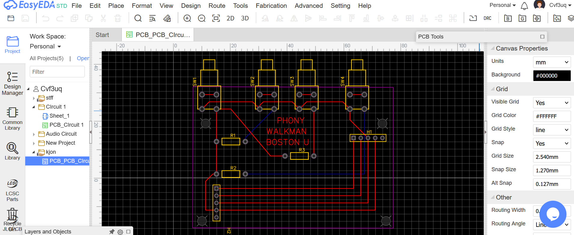
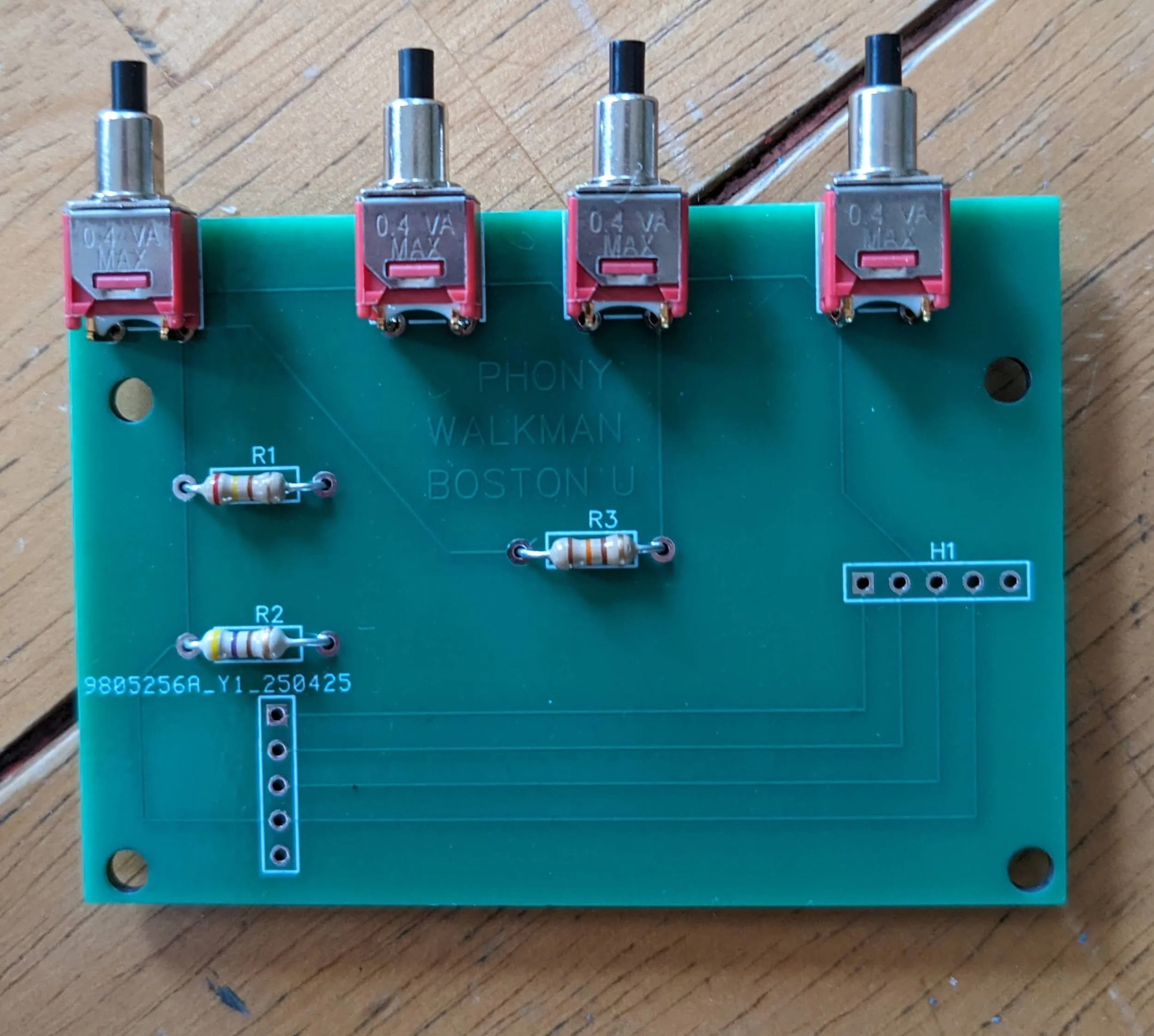
With its simple, if somewhat packed interface and free standard account availability, EasyEDA made this Printed Circuit Board possible, and therefore this entire music player. I drew the circuit diagram using the provided tools, which then automatically exported to a PCB mock-up. Using this mock-up, I was able to properly position the right-angle buttons, resistors, and connector pins for the audio input and output, as well as adjust the PCB size and shape to fit the battery case of the Walkman.
Product Architecture
Making the initial case of the Walkman was a simple matter of studying existing cassette players, CADing the basic structure, and 3D printing the parts.


A short-lived experiment with PETG to form the cover of the cassette case. The color printed far brighter than the filament spool implied, not matching the original Walkman.


The PLA main body of the case, which holds the phone flat and anchors the USB plugin.

A rapidly-printed button panel featuring three working buttons (far left) and a slider button (center) attached to a variable potentiometer. The potentiometer doesn’t yet link to the audio circuit, but will one day be used to control the volume. For the time being, it’s simply fun to play with. The button panel attaches to the case via three 3/16” Phillips head screws.
Aesthetics: Make It Cool, Man!
Since reliable, powerful music players already exist, the Phony Walkman’s success hinged not only on functionality, but aesthetic pleasure and nostalgia. This turned the endeavor into one of industrial design as well as engineering.
Fortunately, the stylized “WALKMAN” at the bottom of the case was a simple PDF download from Google. Unfortunately, because of my clever double-entendre in “PHONY",” I couldn’t just take a PDF of “SONY” and import it into OnShape. Therefore, to mimic the classic Walkman look, I purchased a rendition of the SONY font from myfonts.com. With the font downloaded, I was able to convert Microsoft Word to PDF to get “PHONY” into usable form.
Unfortunately (yet again), OnShape refused to read the PDFs I converted to DXF files, so I had to turn the PDFs into JPEGs, import them into sketches atop the case surface, and painfully trace each and every feature onto the CAD model.
Still, I’m pleased with results!